Finally decided to do some ham radio maintenance …

I had some time over the Thanksgiving holiday weekend to work on some stuff around the house. One of those items was my propagation beacon. It has been cheerfully pumping out a 1 watt signal since getting it back on the air over a year ago, but the last few months have not shown up anything on the RBN.
I didn’t think much about this as the space weather has been really bad and 10 meters really needs good conditions to work. But the longer it went without ANYTHING the more I was skeptical that all was well with the rig. The Reverse Beacon Network is a web tool that allows people to see propagation and to find stations and to see if the signal is getting to certain parts of the world. It is a very powerful tool for chasing DX as well as just looking to see if a band is open to the area where your friend lives that you want to chat with.
This is the WK4DS/B 10 meter propagation beacon. I built it from a dead President HR2600 radio I picked up at the Dalton Hamfest a couple years ago. Actually it wasn’t totally dead, but the output low pass filter was cooked and I had to rebuild it from scratch to get it working again. Once the filter was installed and the radio was outputting RF again, I wanted to limit the output power to 1 watt so I could use it for a beacon. There is information online about how to adjust the output power (I gathered that most everyone else wanted to turn UP the power instead of turning it down like I did…but I digress). The process was actually kinda easy with it being a simple potentiometer and I connected the radio to a wattmeter then on to a dummy load and dead keyed it in CW mode. With the radio working and outputting the required wattage, I proceeded to build the rest of the station. I wanted to keep this build as low budget as possible. The power supply is a repurposed old computer power supply that I added the banana lugs, fuse and switch to. It was a simple matter to reconfigure the wiring to get it to come up when turned on with the switch. I had this in a old dead computer so this was free. I did buy a couple of items though. One being the Hamgadgets memory keyer. I hardwired it to run off of the power supply. (an LM317 set to 3.3 volts solved the power supply problems) and programmed it to start sending in beacon mode upon power up. This was simply plugged into the key jack on the back of the radio. The next thing I did was get an unused SWR/POWER meter that my buddy KG4WBI gave me and put it to work watching the output power so I could confirm the beacon was running at a glance. I did add a couple of LED diodes to the meter so the display is illuminated. I looks way brighter in this photo, but in reality, it is not that bright for whatever reason. It is clearly readable when you walk into the storage room so I am happy. There is also a timer wired to the radio, this is because when the radio powers up with the keyer running, the code sounds odd with this long chirp at the beginning of the characters, but I found that if you pressed the transmit button on the radio, which keys on the transmitter full time, this cleaned the code up and it sounded great. One small problem, the radio would not transmit if this button was on during power up. So to get around this, I bought a programmable timer and set it to close a contact I wired across this switch contacts in the radio after 15 seconds. This allows the whole system to auto restart after power outages and I dont even have to check to see if it started. When the power comes on, it just starts up like a beacon should. This is also why the one button is missing from the front of the radio too. I had to remove it to add the relay wires.
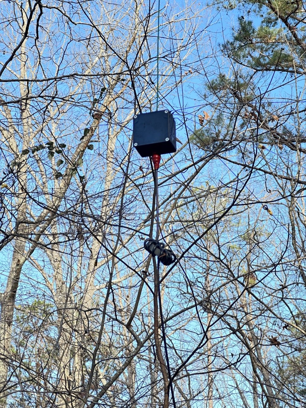
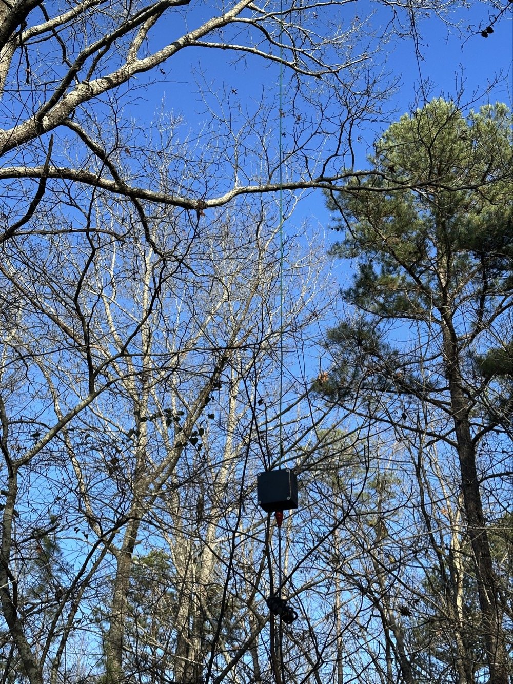
Next thing was to build an antenna. I decided to keep it simple and omnidirectional this time. The old beacon way back years ago actually fed a dipole, but this one should be more meaningful as it will radiate in all directions instead. I simply cut a length of 12ga wire and hung it in a tree about 20 feet up from an insulator and then added some stainless steel tig wire radials to the bottom to get the tune to work. I simply trimmed the wire till I got it close to frequency then started adding radials till the nanoVNA started showing a good impedance match. Then I trimmed the wire to get it as good as possible and ran with it. The wire just goes into the project box and directly to the center pin of a BNC connector and the radials are connected with screw lugs and I sealed it all up with silicone sealant. This was actually supposed to be temporary but as with most things in life, it has seemingly become more of a permanent installation at this point. We will use it till it fails completely then do something different. To limit common mode current and to hopefully slow down lightening, I added the choke you see in the coax going to the junction box. This is simply RG58 coax in a pre-made fixed length from Amazon.
Yes, I know, I know… that electrical tape is not a great solution. I didn’t have any sealing tape at the time and I would like to remind the reader about what the parameters of the original installation were set to. This was supposed to be temporary… I will replace the coax and seal it better…later. (I do think it has some industrial rubber self vulcanizing tape on it, but this was all I had at the time)
As it turned out, this is also where the problem with the beacon turned up…who would have guessed? Right?!?
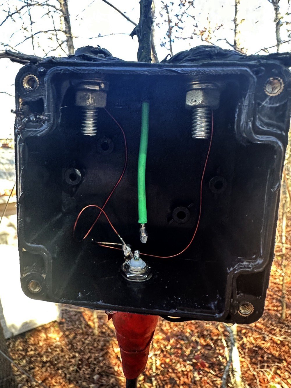
Well the coax was fine, but what I did was connect the nanoVNA to the coax at the radio side to see what the tune looked like. This is a quick and dirty way of seeing if the antenna has a problem. I wished I had thought to take a photo of the screen as it never once had a plot to go into the middle of the smith chart. You know, the part of the chart that has the good numbers on it??? Well, my plot went in nice little circles around the chart from 2mhz to 225mhz! Not one single point of resonance anywhere even remotely close to the center! So I go get a ladder and climb up to the junction box( it is about 8 feet in the air) and pull the cover to see if I can tell if it is dirt dobbers, the coax is bad or what. well, below is what I found…

As you can see, my simply, temporary idea of just running the vertical straight up out of the box allowed the whole system to move around when the wind would blow and eventually broke the solder joint at the antenna connector. Well this explained why there was no resonant point. The SWR was off the scale, but here is the kicker. The power being turned down so low, it didn’t even warm up the back of the radio. It was simple eating all the transmit power in the finals and didn’t care a bit. This radio is rated for 15 or 20 watts output so one watt is almost just bias for these finals…lol. Since I have the meter set to power and not SWR, I had no way of knowing the connector was broken like this, till I plugged a test instrument into it. To fix it I decided to give the wire some help. If you look close you can see a zip-tie I had put in there to help hold the wire in the box, but this was based solely on friction so it worked loose over time. This time I bent a 90 degree offset in the wire and then placed the zip-ties above this bend to prevent placing the load on the solder joint going forward. We will see how long this idea lasts. I soldered the wire back in place…in situ… and then closed the whole thing back up.
[
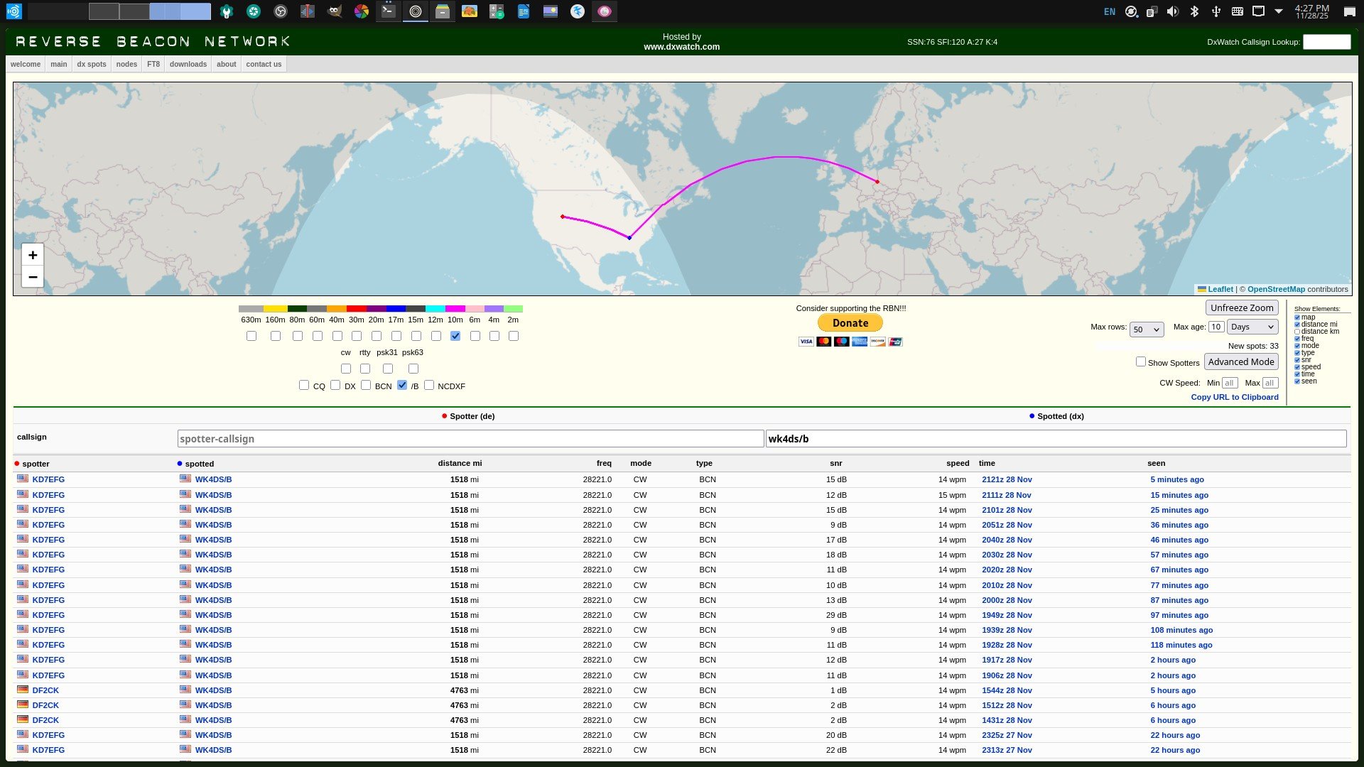
Here is a screen capture of the beacon report the next day after getting it back radiating out of the antenna. It was heard in Germany as well as Utah ON ONE WATT! The bands are not in that bad of a shape so get out there and get on the air! I just wished I had checked the antenna back when I noticed it stopped reporting into the RBN… lesson learned.
73
WK4DS