Fixing the meter lamp on my TenTec Scout 555

Today I finally bit the bullet and opened up my beloved TenTec Scout 555 to see about fixing the meter lamp that was not working…
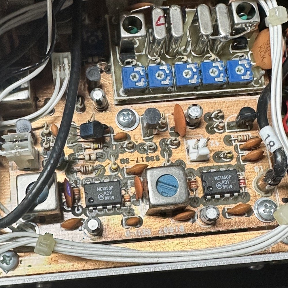
As it turns out, I quickly learned why a lot of people just choose to not have a meter lamp. It is buried really deep inside the radio and almost impossible to repair without fully dismantling the radio. It is also a 10 VDC lamp…I think. The reason I think that is what I found when I started working on the solution to my dead light bulb. I took the radio to the shop workbench and started dismantling and could not find a simple way to access the meter. I called my friend KG4WBI as he replaced his meter in his radio so he had been that deep into his. He basically said something to the effect of God Speed and laughed maniacally. All kidding aside, he did have a some helpful hints and I was glad to talked to him. To “correctly” repair this bulb, which is soldered into the radio mind you, requires completely dismantling the front of the radio in it’s entirety. Armed with this grim knowledge I forged ahead and grabbed a screw driver. Side note about this scout, as seem in this photo below, this radio has the optional Noise Blanker board installed as well as you can see the “Jones” filter in the upper part of the photo with all those adjustments and the crystals. The Jones filter is a wonder of engineering and works really well and is yet another feature that was way ahead of it’s time…
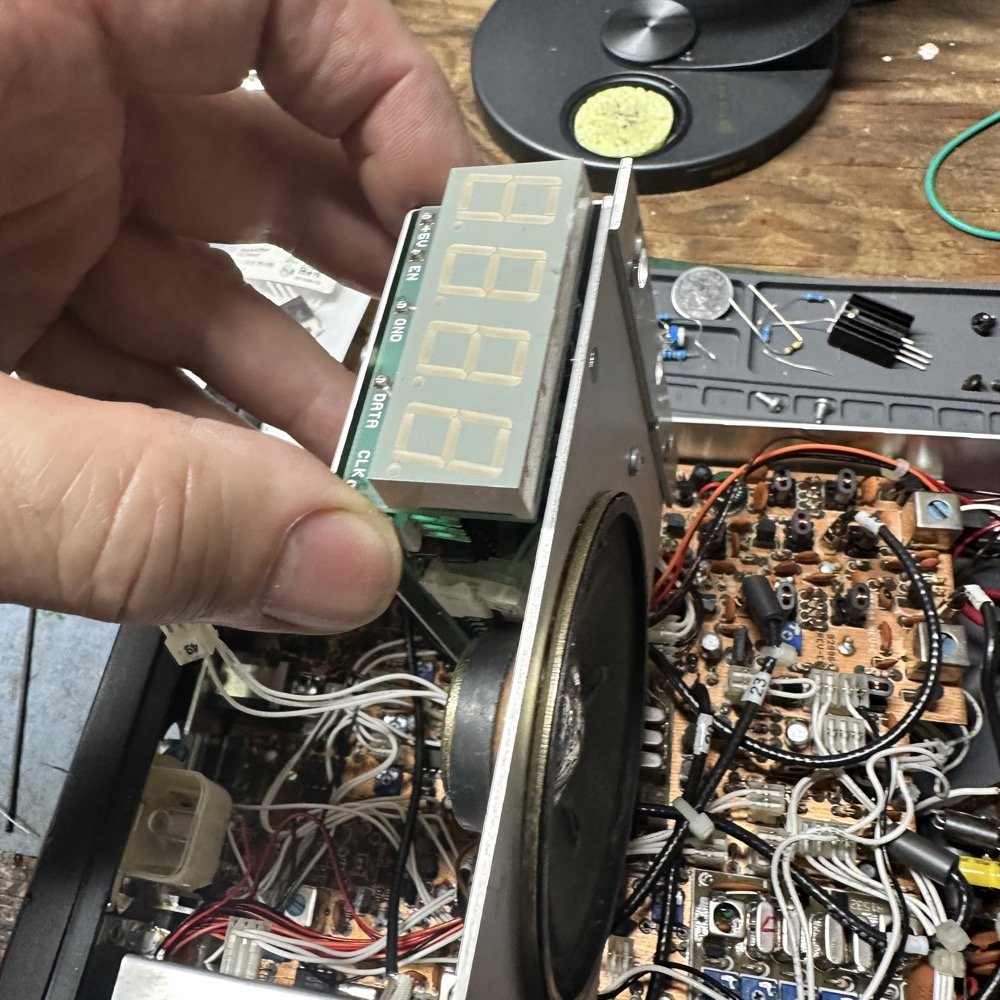
As it turns out, the front digital display circuit board is ALSO mounted to the same board as the speaker. Here is the rub, you can’t tell it by simply looking at the radio when it is assembled. I took the screws out of the plate and attempted to lift it free only to find it was stuck fast in place! I pried and tugged, this way and that to no avail. Nothing I did would let the plate come free. Once I decided that it simply was not stuck and that something else was actually holding it in place, I dismantled the front panel to gain some freedom of movement for the speaker. You see, the speaker is sitting right on top of the meter, so if I can pull the speaker out, then I can get to the meter…or so I thought. As an aside, this radio is built during the heyday of amateur radio and discreet components mixed with early IC chips (mostly in the form of op amps in this radio). This means that the radio is densely packed with circuit boards and wiring to connect them together. Very densely packed to be honest, there is practically no extra space at all.
I finally got the front of the radio dismantled by removing all the knobs and the screws holding it to the chassis and it still didn’t want to come free. Turns out the mic jack and the headphone jack were both still attached to it so it didnt want to move. But I could get it to cooperate a little and with this little bit of forward movement I was able to see why the board would not come free. The display was catching on the front plate… A little careful prying and it slid past the edge of the front plate and the speaker assembly popped free…sort of. It still had a cable that was keeping it from laying out of the way while I worked on the meter lamp. I unplugged the cable and this gave me the room I needed to work so now we could actually see what I was dealing with.
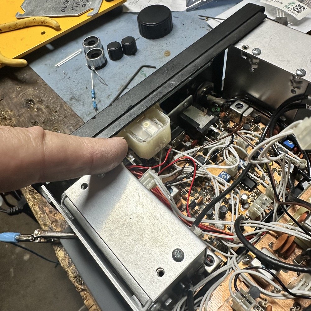
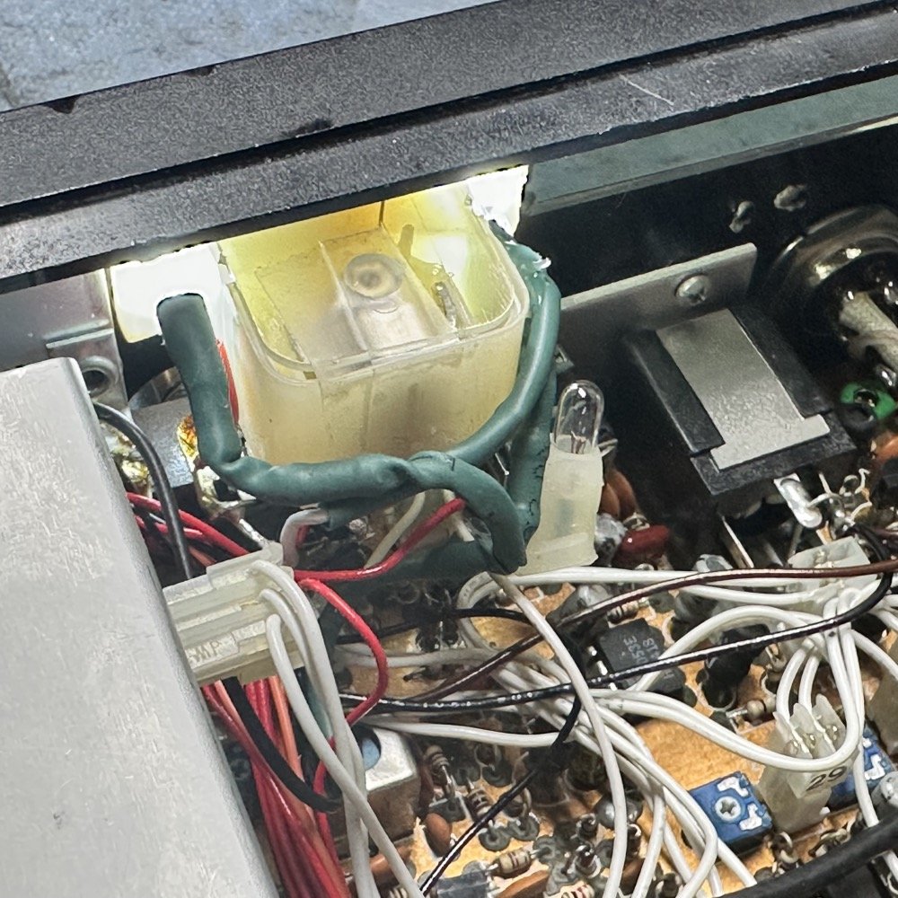
In the above photo I am pointing at the back of the S meter. The lamp is actually on the other side and the lamp wiring is run underneath the meter. Notice that to get to that side of the meter would involve removing the entire main board in the radio along with the PTO assembly(the metal box under my finger). If that was going to be required I had already decided that I would just not have an illuminated meter… Fortunately it didn’t come to that. The PTO in the Ten Tec Scout is a nod to their older designs as it predates encoder style frequency adjustment. This instead has an inductor and the knob you turn will drive a permeable core into or out of the inductor thus changing the inductance and by the same token…the frequency of the oscillator. Super old tech that works really well to be honest.
Once I got to this point, I found the lamp and saw where it was connected to the radio to get power. I didn’t want it to light up unless the radio was turned on, so I needed to find switched power to feed my new “lamps”. You see i used white LED diodes to light the meter instead of an incadecent lamp. While I run the risk of RF noise from the LEDs, I tested them to see what they would do if fed DC voltage before I permanently wired them into the radio. They didn’t seem to cause any problems at all. Either these don’t produce much RF hash or the engineers from Ten Tec back in the day were smart enough to solve this too.
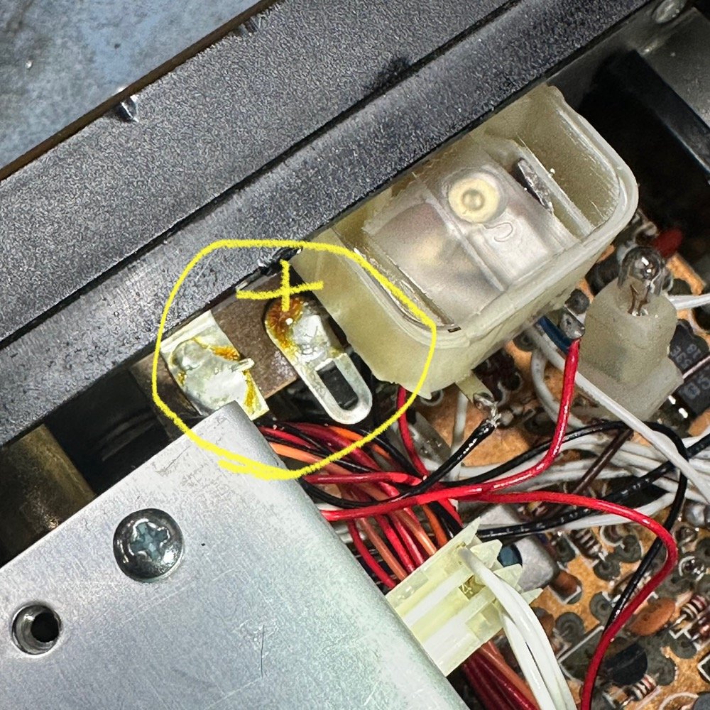
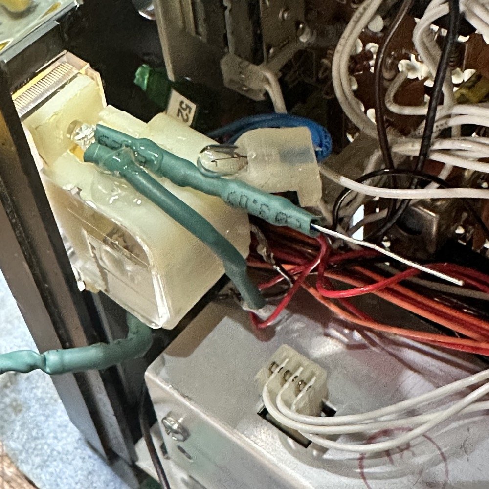
In the above photo you can see the lamp which is in a silicon rubber “holder” that must have come with the meters from the supplier. Rather than risk causing some sort of problems trying to remove this lamp, I simply tucked it underneath the meter out of the way and grabbed a mirror so I could see where the lamp leads went. Turns out they went to the two tabs circled in the photo above. This was good as I could get to these terminals to tie in my new lamps pretty easily. So I grab a voltmeter to figure out the polarity and discover that it is 10VDC and not 12VDC or even supply voltage. I am guessing it is coming from some sort of regulator as it feeds a metric ton of stuff in the radio. I figure it could handle the extra 10mA that I was about to ask of it so I gave it a shot. I am not sure what the original bulb consumed, but if it is anything like other incandescent bulbs I have worked with, it will be many times that of these LED diodes I am about to install.
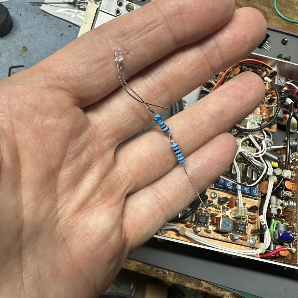
Knowing that full power driven LED diodes are REALLY bright, I decided to turn these down…way down actually. So I started with doubling the resistance I was planning to use, so I soldered up a test set of two 680 ohm resistors in series and one white LED so I could see how bright it would actually be.
This is just for testing things out, once I like the illumination level, I trimmed all the excess leads away and put all of it in heat shrink tubing to insulate it from the rest of the radio. This did however allow me to see what I was dealing with. Turns out that this setup on a 10VDC supply only draws 5mA which is wonderful since I don’t want to damage the regulator in the radio by overloading it with lamps. To be honest, I could have probably halved it again and it would have been fine. The illumination was not consistent since I could only place the LED on one side of the meter and it doesn’t emit light in all directions equally like the old light bulb did. I had to get creative in the placement of the new “bulbs” so that the meter would glow but not look like it had two little headlights in the meter. Turns out this is really hard to do actually as the space it really limited in the raido and I wanted to add another lamp to the system. I was able to get them in the space though as I could simply solder the one on the left side directly to the power terminals and let the legs hold it in place. This worked really well. The other side needed little lengths of wire to get them to reach so I cleaned the side of the meter housing and hot glued this LED to the side of the meter. Hot glue is magic…I am sure of it.
The above photo is what I ended up with to get the resistors and the wiring in place and to keep all of it out of the way so the speaker would still fit when I was done. Notice I left the old bulb installed as I didn’t have a good way to remove the wiring connecting it and didn’t want to risk damage to the radio attempting to do something about it. It doesn’t hurt anything being there so I am good with it just lingering inside the radio at this point, out of the way.
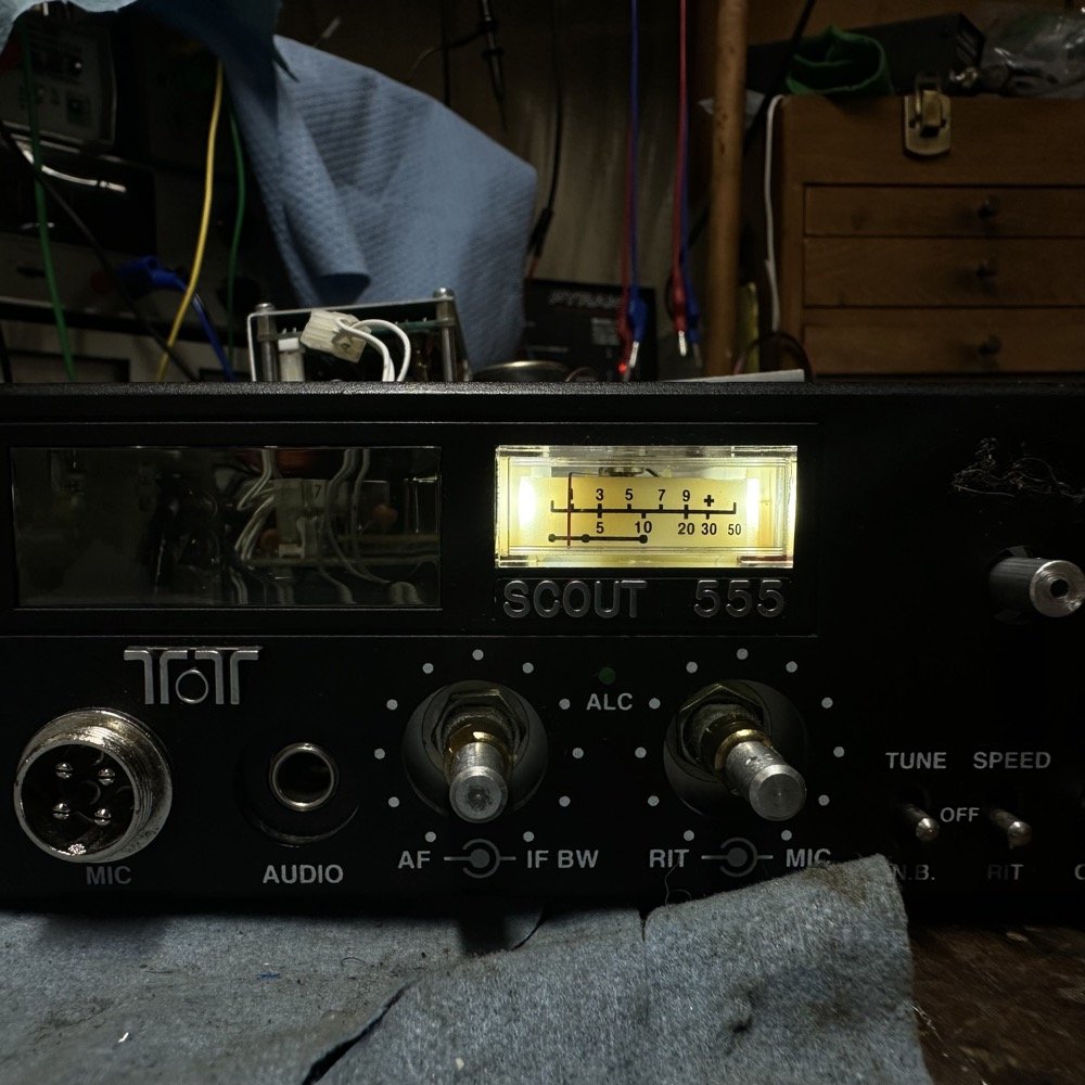
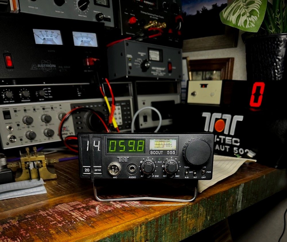
Below is what I ended up with. To be honest, it looks better to the human eye than to the camera, I had to work really hard to get a decent photo of the lamp looking like it does in person. It isn’t washed out in person like it is on the sides in the photo. I am really happy with what I got here and look forward to deploying this radio in the field to see what it looks like at a park on the late shift.

After I finished up the installation of the lamps, I slowly reassembled the rest of the radio and did a couple of little upgrades along the way. One was to file a small flat on the PTO shaft so the set screw wont slip and you dont have to crank down on the set screw to get it to hold on the shaft too. This will save the knob from cracking (which is a known problem with Ten Tec knobs) and I get the peace of mind of knowing that the shaft wont get damaged and prevent the knob from sliding off like it should.
Once assembled, I took the radio to the house and connected it to my main shack antenna and got it on the air to see if it still worked properly since I had just dismantled it pretty heavily. It seemed to work just fine so now it is ready for the POTA parks again but now with a working illuminated display!
Hope to work you soon and 73!
WK4DS
ten techfradiorepairscoutscout 555amateur radioham radiopota