sBitx cooling woes solved!

I think I have finally fixed the heat problem!
Stress testing the new fan on the bench.
The HF Signals sBitx radio is designed to be a passive radio. That is, it is not cooled by fans at all…from the factory. I used it in this state when I first got the radio and to be quite honest about it, I thought it was going to fail due to heat alone. The rear heat sink would get so hot you could not touch it while activating a park. It was crazy, and on top of that, the CPU temp would get into the 50s centigrade and that is really hot for a ARM processor in my book. In all reality, it would self throttle when it would get that hot and would lower the output power and everything would just run ultra slow till it cooled back off. The only way to really get it to go that high was to use FT8, and it could easily make that happen…
So the first thing I did was adapt a computer power supply fan to the heatsink and wire it up with a transistor controlled by a thermistor so it would only run when the heatsink would get to about 105 degrees and once the fan cools this heatsink down, it turns back off so it doesn’t run unless needed.
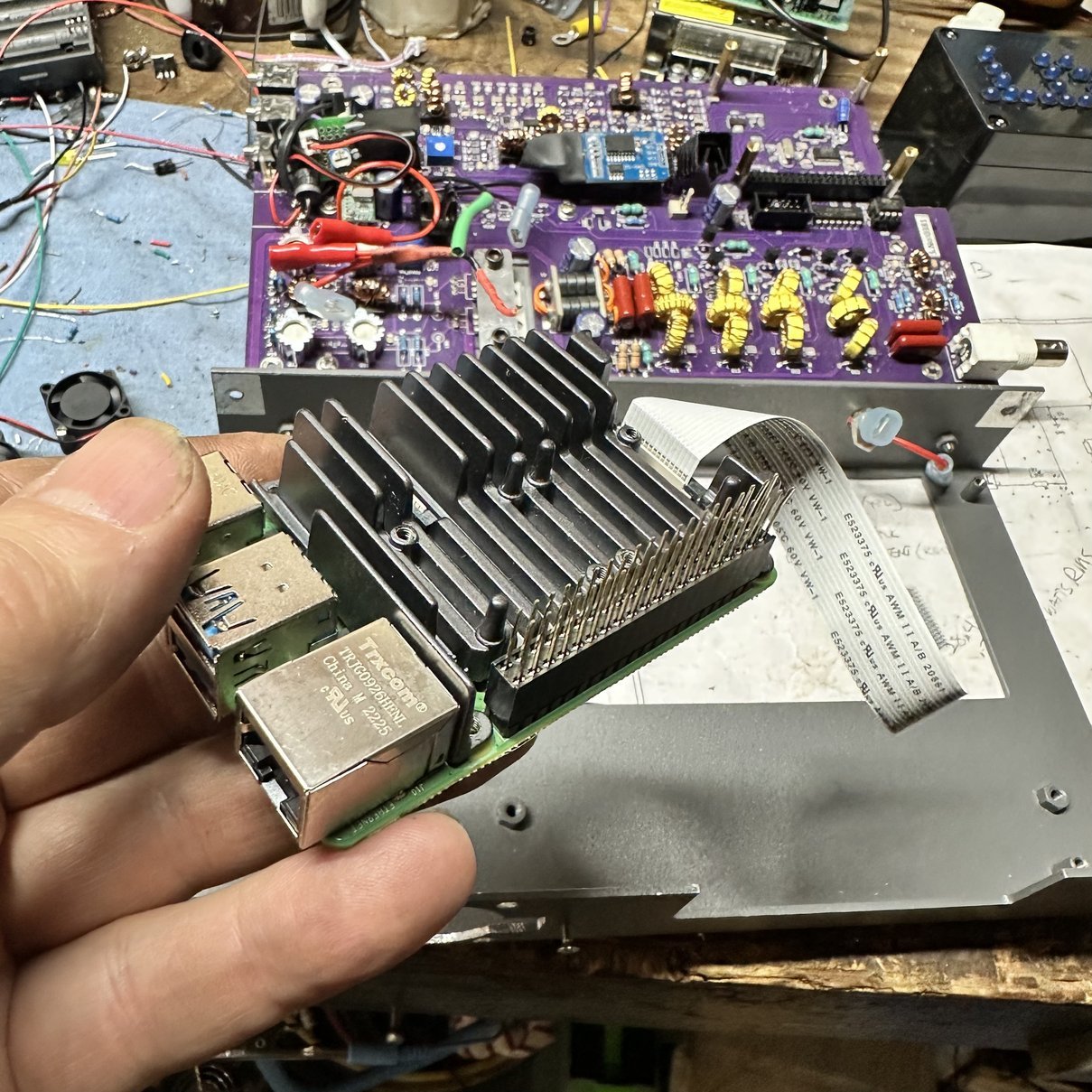
The CPU would still get REALLY hot even with this mod, so I started looking at ways to cool the Raspberry Pi 4 SBC… What I came up with for that was this heatsink/dual fan package. Seemed like the golden bullet for my problem…till it wasn’t. The little fans were really loud and the CPU would still get really hot on long activations and especially with FT8 as well.
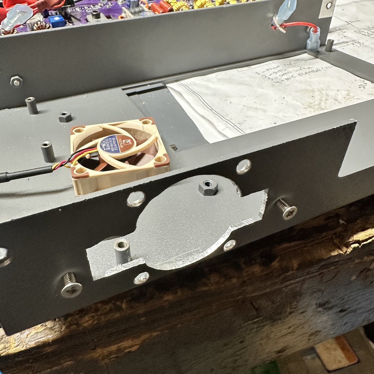
So the next logical step was to find a quieter fan. I searched online for a while and the brand Noctua kept coming up. Seems these guys are specialist in making quiet computer fans. So I did some measuring and chose a fan that would fit on the radio in the space that I had to work with on it.
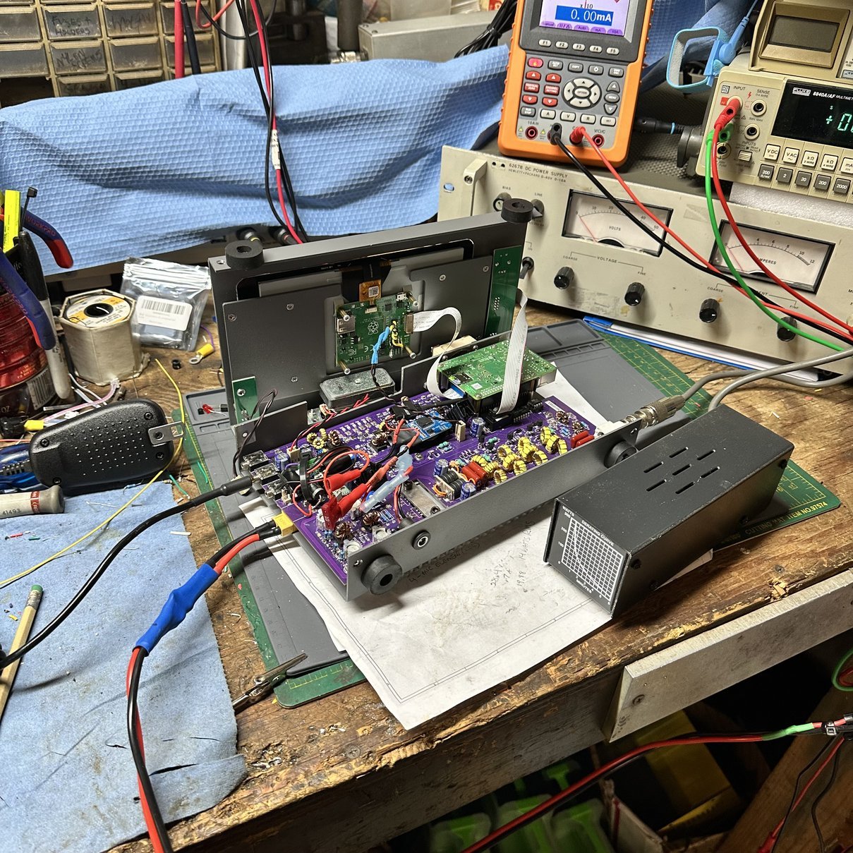
Once the fan came in, I set out to mod the radio to use it. The first thing I had to do was completely strip the housing so I could mod it for the fan itself. In the process of doing this, I stopped along the way to remove the two fans from the heatsink which allows it to breath a little easier and will let the airflow across it better as well.
With the original tiny fans removed, there was a lot more room for air to flow across the heat sink as well. I think this perk alone made a large contribution to keeping the temperature down on the micro processor. Next thing I had to do was cut a hole in the casing to add the fan to the top of the Raspberry Pi area. I simply used the fan to make the template for the holes and drew most of the inner circle through the fan blades with a pencil to get the opening marked for the airflow to occur.
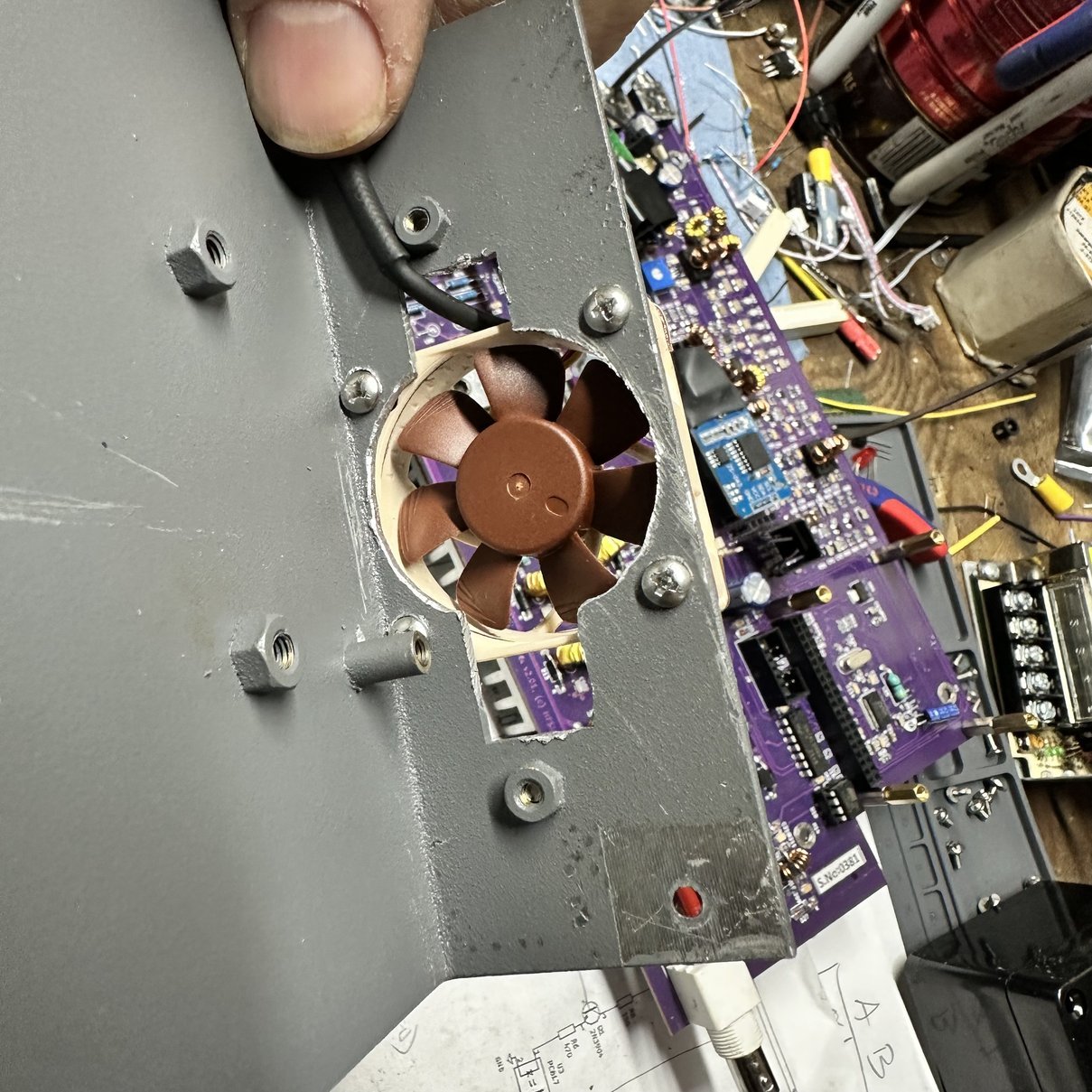
I simply used a file to cut out the opening and a small hand drill to drill the holes for the bolts to add the fan to the chassis. I did this in the center of the location of where the cover was located to access the HDMI ports on the raspberry pie. Due to relocating the pie with a riser, (so I could add the heatsink and fans originally) I was forced to sacrifice access to the HDMI ports, and since I only use it for Park activations, this doesn’t matter to me anyway. (I know, I know… I could have cut out the housing to access the ports, but like I said, I don’t use them anyway so I didn’t bother.) Once I had it filed and drilled a D Byrd everything because the chassis was aluminum and it made a huge mess. I added the fan and blocked off one side of the opening with a piece of plastic that I had to force the air to flow through the radio instead of around it. I left the other side open to make it like a conduit passage to get the power cable inside the radio, so I can connect it to power.
I also took this opportunity to clean up some of the internal wiring and adjust the gain on the SSB microphone preamp that I had installed. There is another blog post that talks about the SSB preamp circuit more. I attempted to adjust it by listening to another radio with the sbitx connected to a dummy load so the RF would barely radiate. It worked surprisingly well, I plan to use the SBX for single side band operations in the near future to see how it sounds on the air. I hope it works at least…lol. It sounded pretty good on the test bench.
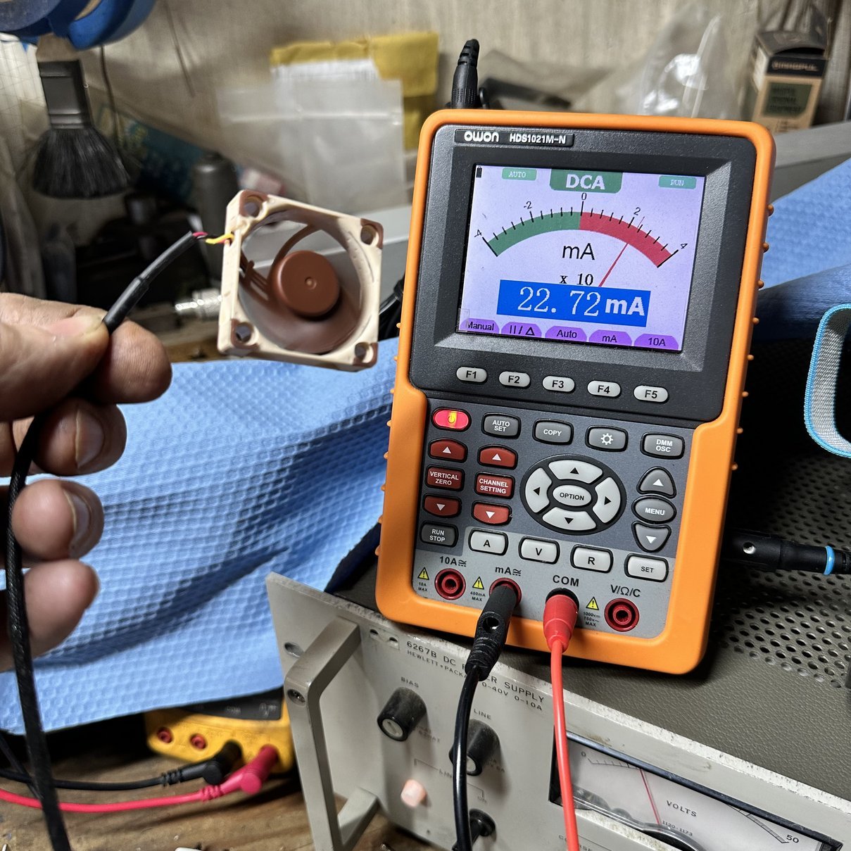
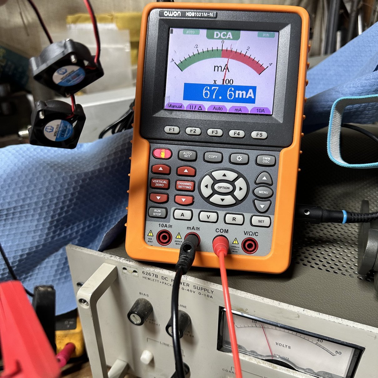
With the fans removed and the radio dismantled I was able to set up a simple test station to measure the current draw of the old fans and compare it to the current draw of the new fans at 13.8 VDC. As you can see from the above photo, the current draw is almost 3 times that of the Noctua fan and the Noctua performs significantly better than the (2) 25 mm fans that I was using. I find it interesting to see things like this when I have the opportunity to do so. You can also see my new Hewlett-Packard 6267B DC power supply that I picked up at the Orlando HamCation hamfest recently, this thing is awesome on every level. I think I will do a write up and discuss what I like about this power supply and the one thing I don’t like about it. HaHA
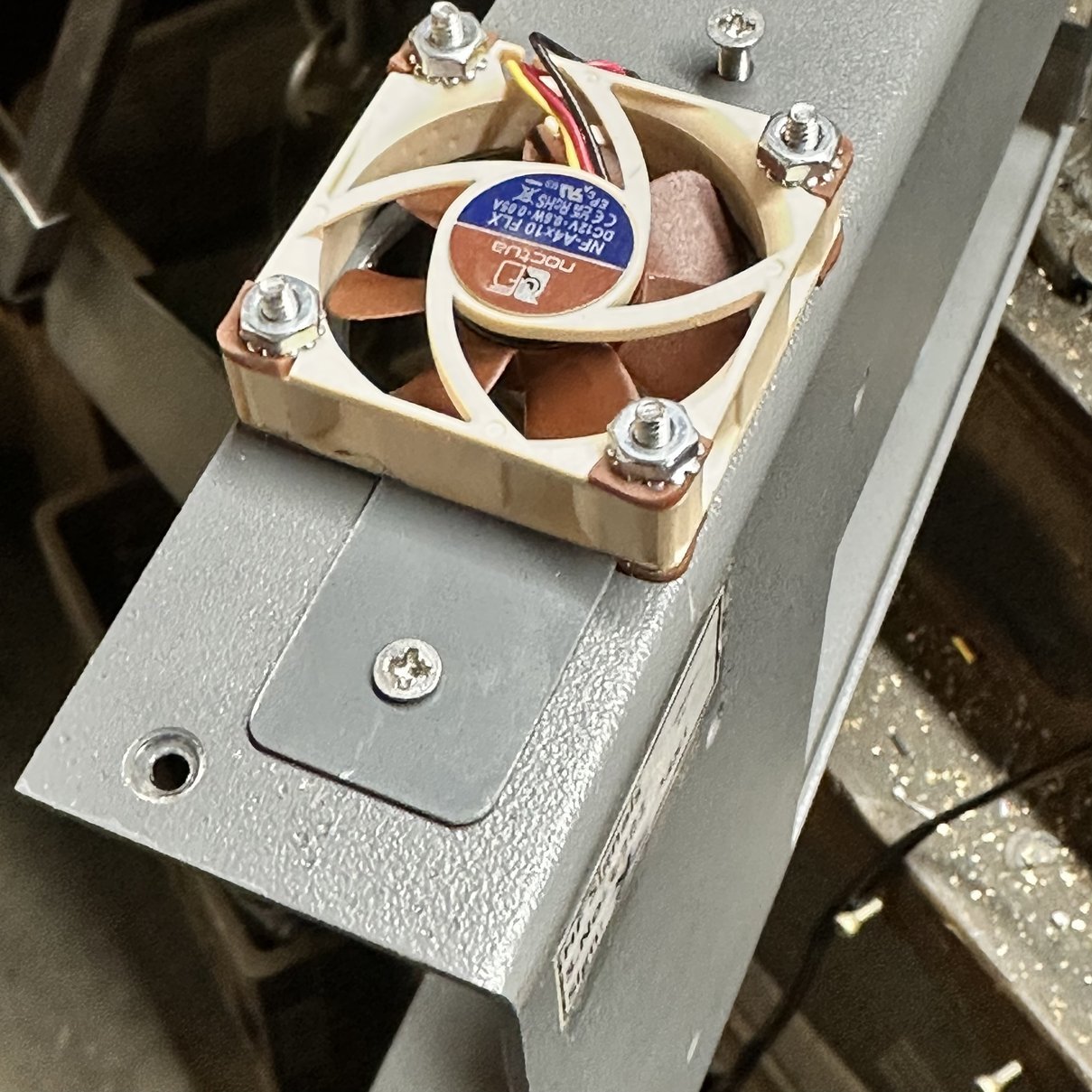
Once I had the hole cut out, I proceeded to bolt the fan in with 4-40 screws. I inserted the screws from the inside of the case, heading out, so that the bolt shanks would not protrude into the interior of the radio. This prevented anything from short-circuiting against the fan screws that might touch them on the inside of the radio housing… just to be safe. I used tec-lok nuts so that they wouldn’t work loose and the bolts wouldn’t drop into the case either, and at some point, I may go to the hardware store and get some decorative acorn nuts to cap it all off with just for fun. Once the fan was bolted to the housing, I cut out a small piece of plastic to cover 1/2 of the opening on one side and used the original screw and screw ferrule to bolt it on with, giving it a nice clean appearance on that side, I then allowed the other side to remain open, as I had mentioned earlier, this became the conduit access essentially for the wire to get inside the radio, so I could connect it to power easily.
By switching to one 40mm fan over two 25mm fans I have a 28% increase in fan surface area alone. This is like adding another fan essentially. Sometimes less is more I guess.
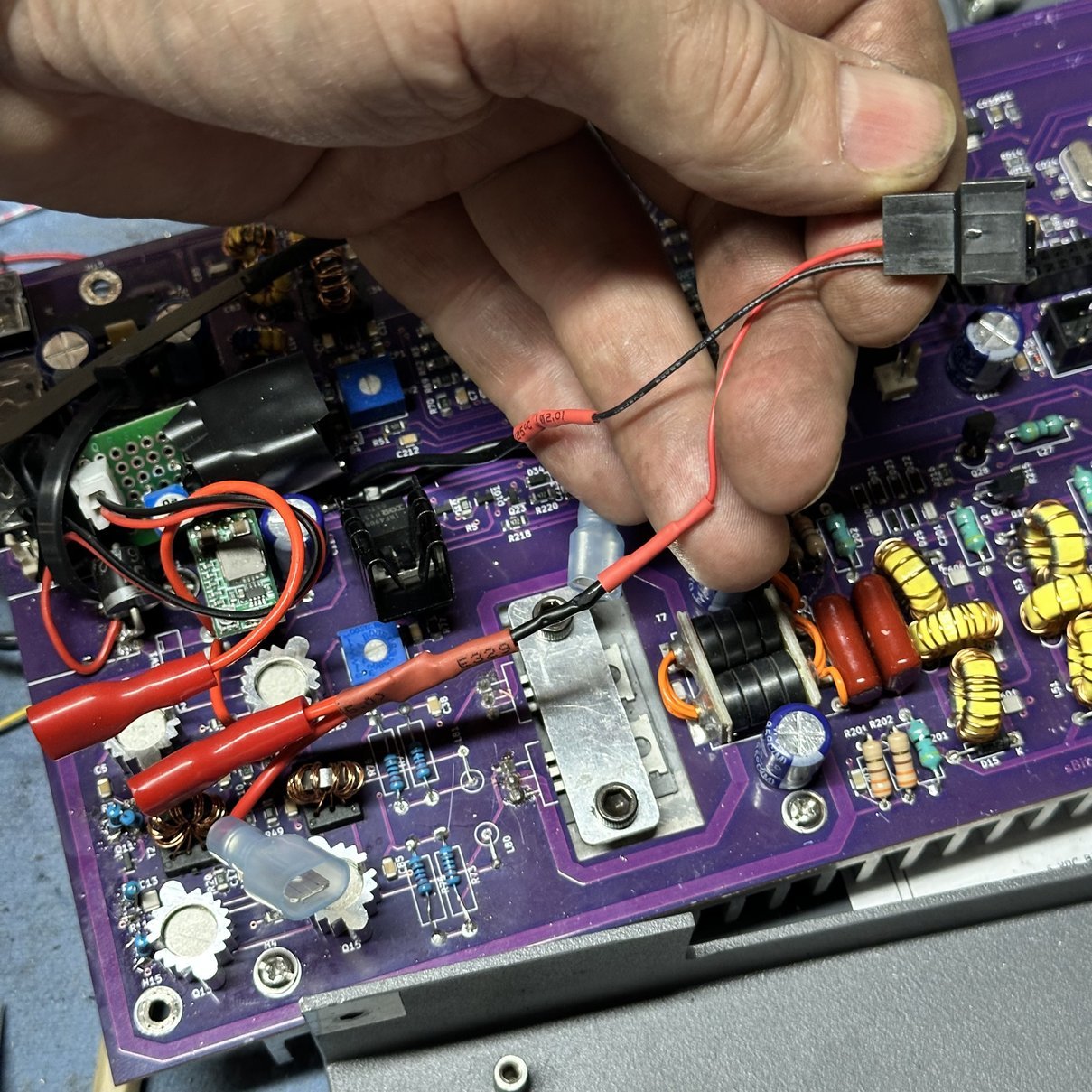
Once all of the mechanical work was done to actually attach the fan to the casing, I proceeded to do the electrical by replacing the old 25 mm fan connector with the connector for the 40 mm fan and soldering it in place into the wiring harness. Then it was a journey of reassembly of the radio so that I could power it up and test it to make sure everything worked as it should, before finally buttoning up the system. I routed the cable underneath the Raspberry Pi as there was actually room for it now and it allowed me to get it out of the way and keep it away from the RF circuitry so that it would not pick up RF energy.
After all that, I reinstalled the Raspberry Pi and connected up all of the display connections so that I could power the radio on and test it. The radio performed as it should, and I did the final assembly of the chassis so that I could stress test the radio to see if the new fan would actually do the job that I had planned for it to do which was keep the Raspberry Pi’s CPU cooler than the original fans and heat sink combo had done by their self.
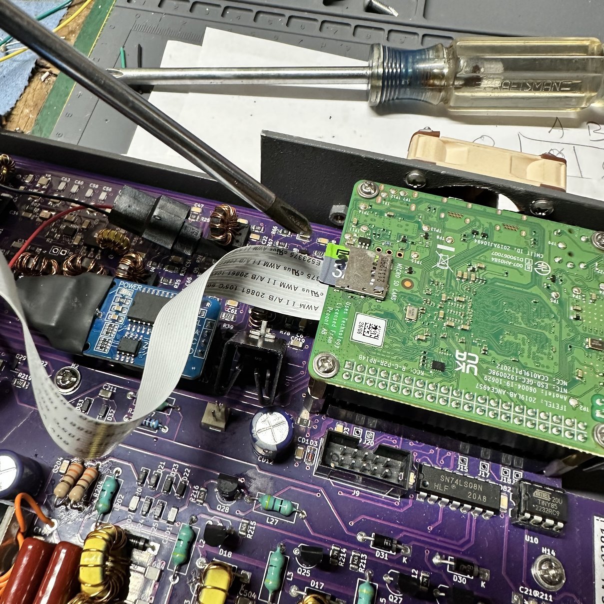
Another quick side note for people just getting into this radio and you have found this blog post, is that the picture below shows the memory card plugged into the Pi and where it is located inside the radio. You literally have to open the radio casing, cracking it in half so to speak, to access the memory card if you wish to replace it at some point This is the one thing that really bugs me about this radio is that there is no externally accessible way to replace the micro SD card without disassembly of the radio. It is not a deal breaker by any stretch of the word, but it is something to consider. Several people have figured out how to run the Raspberry Pi off of a USB memory stick instead and choose to operate the radio in that manner, but I do not do that and use the microSD card for my operating system. I will occasionally clone it and replace the one in the radio as there is a finite number of write cycles that you can perform on these memory cards before they are corrupted or at least become less reliable. Just keep that in mind and plan on cloning the memory card about once a year and replacing it if you plan to keep these radios in your arsenal for any period of time and use it regularly. Actually, I subscribe to the idea of immediatly cloning the memory card as soon as I get the radio and then every time I upgrade the OS to the newest version, I will make a new copy then as well. This gives me many copies of virtually brand new memory cards should the one I am using go down for some reason like a corrupted card. I can simply put the previous version back in, clone it immediately, then update that card to the latest OS version. Then I am back in business like nothing has ever happened.
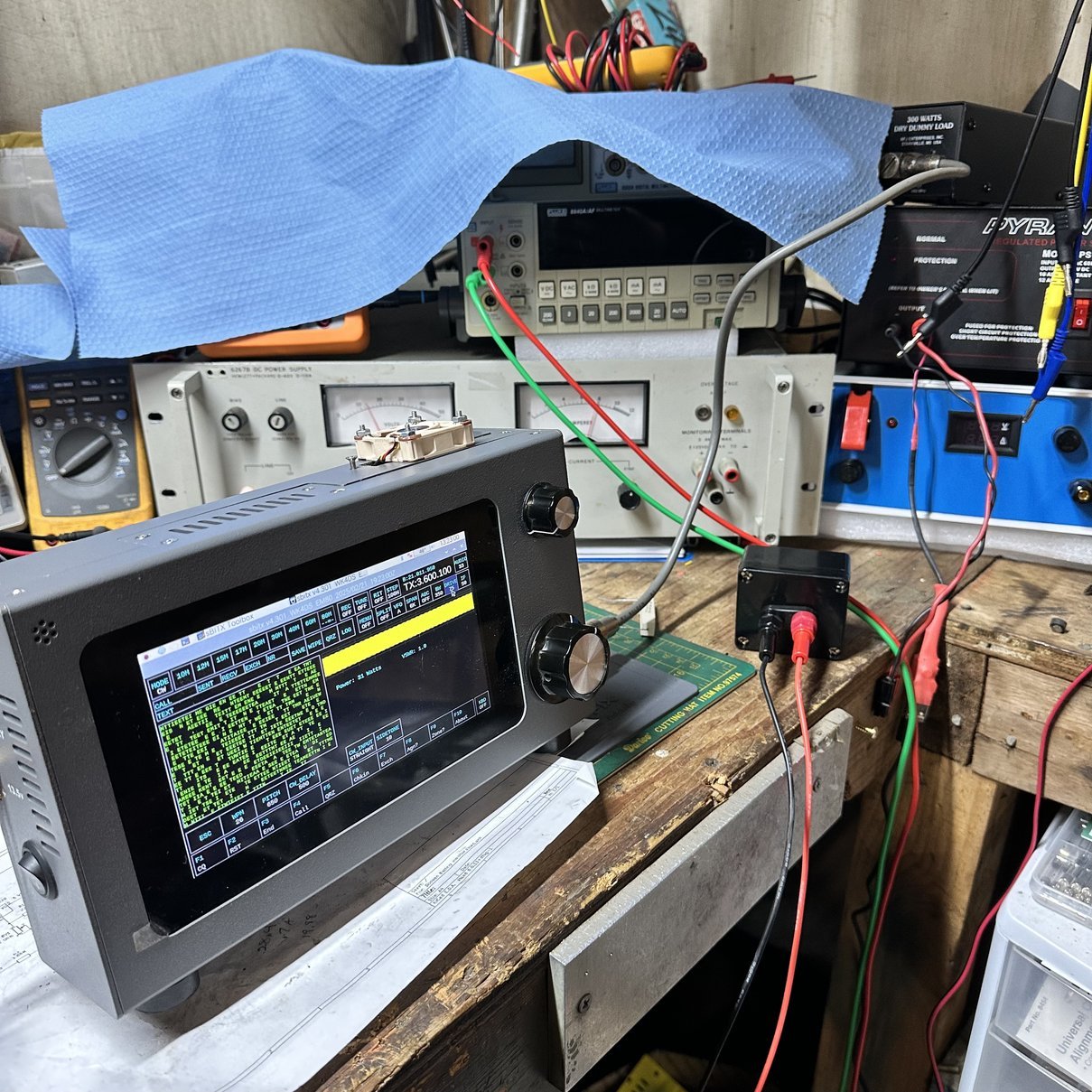
As you can see above, I hooked the front panel up and connected a dummy load so I could check the system and confirm it works prior to final assembly. This is something I have come to learn over the years…I make mistakes. So knowing this I now check it under power prior to final assembly so I can make darn sure it works right… haha. You can also see…kinda… how close the screws for the Noctua fan are to the Raspberry Pi SBC. Well, really you can’t tell all that well, but it is close, so running the screws from the inside out was a good call.
Once assembled, I connected it to my new-to-me HP 6267B DC power supply I picked at HamCation, set it to 13.8VDC and limited it to 10 amps then juiced up the radio. Once fully booted and the application running I wanted to stress the system so that it would heat up and see how the new fan did on keeping the CPU cool as well as test the auto fan control circuit for the heatsink fan as well just to make sure it is working like it should.
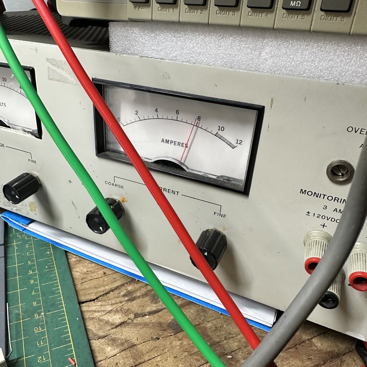
Well, the easiest way to do this is to use 80 meters. This radio has more output power on the lower bands than the upper bands so to draw more current…that is heat up the semiconductors faster, the lower the band should be set. I went to the bottom and chose 80 meters. I can actually get well over 40 watts out of it on this band, but I don’t think it is really linear when set that high so I pull it back well below the maximum and today that number was 31 watts on the display. I didn’t have an external watt meter handy so we will just go with 31 watts. The power supply was showing almost 8 amps at this level so I belive it was at least 31 and maybe a little more in reality. The radio draws a little on receive and the fans pull some as well so the total draw was 96 watts of energy, and if you figure 1/2 that is turned into RF, that would be 48 watts right there…we all know that the radio consumes some of that energy though so the transmitter was probably outputting between 31 and 36 watts of real power to the dummy load if I had to guess.
With this running, I hooked up a key and set a weight on it. (Actually it was my spool of solder…) and just left it in CW ,dead keyed into the dummy load at “31” watts and walked away. The dummy load can handle 100 watts at 100% duty cycle so 31 watts is basically a joke to this thing. Having this knowledge, I was confident it would not hurt the radio or the dummy load while performing this test.
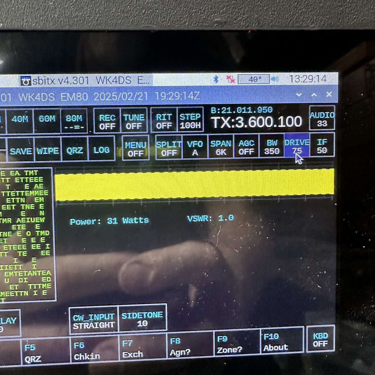
I let the test run for almost 10 minutes before realizing that I should grab a couple of quick photos showing the output power and the timestamps on the radio, to show you the temperature which is right beside the timestamp at those periods. Now to be perfectly fair, I could have cheated this and turned off the transmitter between the two time stamps, but I didn’t. I left it on and just let it run to see how hot the CPU would get. As you can see, it peaked out at about 39 to 40° C and never really got any warmer. The temperature would fluctuate between 41 and 39, back-and-forth, and I assume basically because the transmitter heatsink fan would cycle on cool off the transmitter rear heat sink then cycle off and that would allow the interior of the radio to warm up a couple of degrees (while the rear fan was off) before it would cycle on and cool down again. This is the coolest that this CPU has run under heavy load conditions since I have owned the radio. This fan is a good solution, if you don’t mind a little bit of fan noise while you operate. It is not a completely silent fan, but it does reduce the noise level dramatically from those little 25 mm fans that were in the radio earlier.

I am really happy with how this turned out and dont mind the little fan on top of the radio at all. It works really well too, so there is that. HaHa. Thank you for tagging along on this little journey, until next time, get your radio out and play with it.
73
David - WK4DS
#block-yui_3_17_2_1_1740191522160_26236 .social-icons-style-border .sqs-svg-icon--wrapper { box-shadow: 0 0 0 2px inset; border: none; }
[
](https://www.youtube.com/@HamRadioToday)[
](https://www.instagram.com/ham.radio.today/)[
](https://www.facebook.com/groups/hamradiotoday)[
](https://www.tiktok.com/@ham.radio.today)[
](https://discord.gg/XTxk6MuqAU)